Friday, December 14, 2018

Week 14

Week 14 Update

For this week, we decided to focus our attention on wrapping this semester up. We began by starting our project report in order to get on outline. We also needed to upload all of our CAD for everyone to see and use. The Bogie Teams were all in need of a track to mount their assemblies to check for interferences. 

We also kept in mind that we were behind on some FEA. Due to the end of the semester quickly approaching, the FEA department has been lacking. We had been running into multiple problems with our assemblies (multiple interferences, poor mates, etc) and we needed to take time to correct these. As mentioned in the third presentation last week, we seem to have run out of time. Although most of our designs are finished, without the FEA we cannot make them official. For the rest of the week, we will both focus on the FEA in order to provide a more concrete project report.

Thursday, November 29, 2018

Week 13

Week 13 Update

This week's focus was on completing our models for the semester, and preparing for our third presentation. David continued his focus on the junction and trying to get that finished before the third presentation. Evelia worried about the column assembly that needed to be rebuilt after Futran's files failed to give us proper simulations. However, we fell behind on analysis due to some collisions and interference within our assemblies. We were not able to deliver as much as we would have liked to on the presentation, but we are happy that most of our designs are being finalized.

In the presentation we mentioned that our design for the third rail and track system is now finalized. the junction is pretty close to completion. As we mentioned during our presentation, our goal for the end of the semester is to have all analysis finalized to support our design so that we can focus our attention on redefining and optimizing our own designs the following semester.  Below is the presentation we put together. 

Tuesday, November 20, 2018

Week 12

Week 12 Update

For this week, we continued our design of the junction as well as the column assembly. David was in charge of the continuation of the junction and Evelia took on the task of creating a new column assembly now that the column was rebuilt. 

Evelia found that none of the files provided by previous semesters were working. This meant that we didn't just have to rebuild the column, we also had to do all parts of the column assembly. Evelia plans to have this done before the next presentation in order to provide some FEA to the solar team. Below is an image of the column assembly that we will be redesigning.


A few questions we wanted to address:
  • What are the overall dimensions of your track going to be? 
    • For just the junction section it looks like it's going to be ~2.7 m tall, ~3 m long, and it looks like 5.5-6 m wide at the end of the split, but this won't be fully known until the model is finished.
  • How far will the curved section of your track be? 
    • We plan to just do the 3 meter section of junction, so if we are able to make it compatible with the current wooden track it will be able to go straight for ~6 meters, or straight for ~3, and then turn for another 3.
  • Will your track design mimic the layout of the old metal full scale track that is in the back of the shop?
    • We don't think so, we are mimicking the wooden track with hopes to make it out of metal instead of wood.
  • I am still curious on how your team plans on supporting the Y-section of your track? 
    • The design is still in the works, but it is either going to be supported from the column cross-beam that is supporting the track at the start of the junction, or have its own support column from below.

Wednesday, November 14, 2018

Week 11

Week 11 Update 

For this week, we decided to continue on with our design of the junction as well as providing the full column assembly so that FEA could be performed. We want to be able to finalize our designs as soon as possible to focus on working with the analysis to provide to other teams (such as the Solar team). We are still on track to presenting soon, and are hoping to have many of our designs finalized with little to no changes made. Below is our new track assembly and the new dimensions.


For this week, Evelia focused her attention on updating the third rail and redoing the analysis to check if there were any changes. The reason for the update was due to the Interface Bogie Team's newest design. Their switching wheels on the bogie are standing at about 20.7" (525 mm) above the track. Our original supports were 10" and now they are about 3.88" (90.52-mm). The FEA for the new design can be seen below. We will continue working on the third rail and junction as well as getting the FEA done for the column soon. 


New FOS is 15


Maximum displacement is 0.066" (1.685-mm)
Von Misses Stress Analysis


Wednesday, November 7, 2018

Week 10

Week 10 Update

For this week, we decided to focus on several things. First we focused our attention on:
  • Rebuilding/Re-designing the vertical columns found in column assembly
The column assembly that was provided to us seemed to run into issues whenever we tried to perform FEA. So, we decided that our best option was rebuilding it. We went through two revisions before we were able to properly construct the column again. Below is the image of our new column as well as the new assembly. We will be running FEA as soon as possible in order to provide the Solar Team some information about how much our columns can withstand.
Full Column Assembly (Right) and column component (left)


Second order of business was:
  • Creating a segmented track 
We were given the idea by Ethan and Dr. Furman to create a segmented track instead of bending it. The reasoning behind this was manufacturing costs. It might be too difficult and expensive to bend the track and the components that go along with it. So, we have decided to create a segmented track. We have two different designs for this, as can be seen below. Once we have a set design, we will do some FEA to compare the designs.


Figure (left): Segmented track & curved sheet 


 Figure (right): Design #1 for segmented track


Figure (left): 5 segment track design w/ curved sheet 

Lastly,
  • Continuing our design of the junction 
The junction is a work in progress and David has done a great job in showing our newest design. Below is what we have so far. Work is still in progress to modify the truss structure to accommodate the additional width from the track.
Preliminary junction assembly.


ALSO, we have decided to use a 2x6" tube rather than the 2x8" in order to give the bogie teams more space as well as minimize material use. 

Wednesday, October 31, 2018

Week 9

Week 9 Update 

For this week we decided to continue on with our design of the junction. David has been CADing up some ideas. We were worried about the spacing between the track and between the support columns within the inner portion of the guideway. As of now, we are working with the cross-section shown in the image below. This track is made of three key tubes that are roughly 2x8" (top and bottom) and 2x4" (vertical). After some discussion with Ethan and Professor Furman we are thinking of making the top and bottom sections 2x6". This would lower the cost of materials.

Image 1 (above): cross section we are planning on using for our track 
 The junction design we are currently working with requires bending (seen in image 2). After some discussion, we are thinking of implementing welding straight sections rather than bending. This is due to manufacturing costs. For the next week or so, we will be researching manufacturing costs for both, but are leaning more into welding straight sections to form a curve (image 3). 
Image 2 (Above): Junction design that requires bending of our rail 

Image 3 (above): Welding of straight sections. A thin metal sheet would be attached on the inside portion of the curve to create a smoother surface. 
Another thing that we are focusing on this coming week is working with the solar team to get an FEA for the column structure on which the solar panel structure will be mounted. When we tried to perform FEA on the provided files from Furtan, we had some issues due to bad CADs. However, we are hoping to rebuild these so we can provide the Solar team with something soon. 
We were finally able to present this week, Presentation #2 is posted on our week 8 blog!
We are currently on track with finalizing our design for next semester and will be looking into manufacturing costs very soon!   

Wednesday, October 24, 2018

Week 8

week 8 update

 For this week, our team decided to focus our attention to finishing up whatever was needed for the presentation. FEA was performed on the third rail in order to finalize our design. Our results and comparisons can be found within our presentation. We are also moving on to the design of the junction. We are still working with how the tracks will intersect and are taking heavy consideration to Ethan's design as well as other team's ideas. We want to make sure that the Guideway provides a smooth, comfortable ride and the only way to achieve that is to have our design match up the bogie's design perfectly. As we have stated numerous times before, we are looking to avoid having any mismatch between teams. 

We would also like to point out the dimensions shown on our slides will be changing. We had originally given the teams the dimensions we had from Futran, but since we are changing the track design in order to lower the cost and make manufacturing more simple, our dimensions have slightly changed. As of this moment, we are keeping most of Futran's track the same, but as we design the curve part we are finding that some parts need to be redesigned. 

ALL TEAMS WILL BE PROVIDED THE NEW UPDATED DIMENSIONS ONCE THEY ARE REVISED AND FINALIZED BY US. 

Below is our second presentation


Wednesday, October 17, 2018

Week 7

Week 7 Update 

This week, we decided to continue our design work for the curved section of the track. Our presentation will be next week, so we are trying to meet that deadline. We want to finish most of our design by then so that we can continue to move on to analysis and finalizing our design. For next semester, we want to focus on getting all manufacturing done, so having the design finalized soon is crucial to this. As of right now, we have the design of the third rail finished. We are going to be going with a triangular design as this would be more effective than having a diamond shape (figure 1). We are hoping to have some FEA done by the end of this week (10/19/18) in order to prove that our triangular third rail is our best choice. The purpose of the third rail is implemented in order to assist the bogie with turning. The supports shown in figure 1 are most likely going to be welded on. 

Figure 1: The design of the third rail we will be implementing into our design 

Moreover, our next move is to start designing the junction in order to run some analysis on that as well and add it to our design. Once we have the third rail, curved section and junction, we can start finalizing our design. Since we are already halfway through this semester, we want to start finalizing our designs in order to stay on track for next semester. The junction track is shown below in figure 2.

Figure 2: The design of the junction we have done so far  

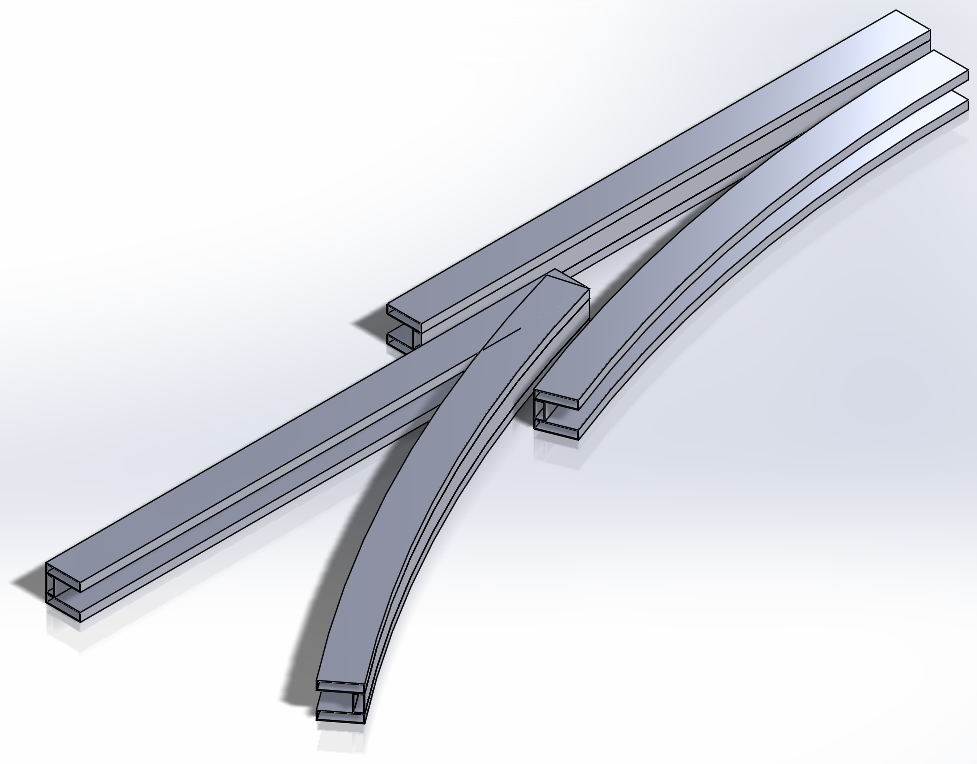
Also, in figure 3 we show how the curved track plus the third rail should resemble. Again, we are still borrowing the Futran track specs and adapting them for our use. The curved section was the reason behind us switching our track design from the cross cross-section to the 8x8 cross section. Futran's original track was going to be too difficult to manufacture, especially the curved section so we decided to change the design. However, the rest of the track will remain very similar to Futran specs, as can be noted in figure 3 below.

Figure 3: Curved track plus the third rail concept design  

For next week, we are going to be focusing on analysis and getting our presentation finished. We want to be able to present new information, so analysis is very crucial for this. We will be working on familiarizing ourselves with ANSYS in order to proceed with analysis. 

Reminder: If we are able to get enough funding for our track, we are going to be making the junction portion of the track out of steel. The straight portion made out of wood that was left behind by previous teams will remain and be used. We are working to make these tracks (wooden and steel) compatible enough to have the bogie drive on it. We definitely want the third rail system to be made out of steel though, as the summer team did not have successful results with their wooden rail. 

Wednesday, October 10, 2018

Week 6

Week 6 Update

This week we decided to focus on designing the curved section along with the third rail. We wanted to design the third rail because we need to analyze it soon. We hope to have this completely done by the time presentation 2 is due. Below we have attached some designs we are considering for the third rail. In the designs that are solid, the supports for the rail will be welded on. If the designs are hollow, the supports will be bolted on. All arrows in images point to where the route-selection wheels make contact with the third rail. 

 Image 1 (left): This image shows a diamond-shaped cross section for the third rail. 
Image 2 (right): This shows a diamond-shaped cross section that is hollow (made of sheet metal). The supports would be bolted on. 
Image 3 (above): Shown is the triangular cross section made of sheet metal
 Image 4 (above): Show is the overall look of the bent railing. The solid diamond-shaped cross section is displayed
Image 5 (above): Image shows a solid triangular-shaped cross section for the railing

The curving track portion plus the third railing is still being designed, but we will most likely have it done by the end of this week (10/12/18). 

We are also getting a lot of questions from other teams and would like to re-address them on here:
  • Can we make the gap more than 4.8 inches?
    • No, we are trying to keep the bogie as stable as possible. Also, the wooden track dimensions are NOT Futran dimensions, and for the steel portion we plan to use Futran dimensions because the bogie is designed accordingly to that. 
  • How will the wooden section and steel section (junction/ match up?
    • The wooden section has different dimensions than the steel, but that should not be too much of a problem. As of now, we are going to use the beams made of sheet metal as shown in image 6 below. This cross section is 8x8 inches and we are planning to add whatever is necessary to the wooden track to match this cross section. The wooden track is made up of construction lumber with cross sections of 1.5x7 and 1.5x5.5. Also, the steel portion will be taller because it will include the third rail, but that should not be a problem with the wooden part because it does not need the third rail added. 
 Image 6 (left): The cross section we are planning to implement on the beam 
  • Will the bogie be able to clamp onto the track?
    • Yes! We are currently designing for this to be possible by changing the track. The cross-section that was provided by Futran is shown in image 7 below. This cross section is problematic because it will cost too much to manufacture, so we are using the cross-section shown in image 6 above.  Image 8 below shows that the 8" x 2" rectangular steel tubing we are planning to use for the new cross-section design is capable of being curved to suit our junction and curved track sections.
 Image 7 (left): The cross-section of the beam, taken from Futran's design

 Image 8: 8" x 2" steel rectangular tubing bent to an outside radius of 58' 4" by Longero.

Wednesday, October 3, 2018

Week 5

Week 5 Update

For this week, we decided to focus on dimensions and design of the third rail system. 
For our dimensions, we are currently going with what Futran was able to provide us. Below is a table with the different dimensions  and figure 1 shows where those dimensions are placed. 

Table of Dimensions

Dimension #Millimeters (mm)Inches (in)Notes
152020.47Space between the outside supports
21224.8Dimension of the gap
32007.87Dimensions of the top and bottom of the cross beams that support the wheel
42258.86Dimensions of sides of the cross beams that support the wheel (plus the thickness of the sheet metal)
52208.66Dimensions of sides of the cross beams that support the wheel (minus the thickness of the sheet metal)
656622.28The height between the cross beam and top of guideway (plus sheet metal thickness)
756322.17The height between the cross beam and top of guideway (minus sheet metal thickness)


**All dimensions from Futran


Figure 1 (above): Where we were able to pull the dimensions from 

We are going to be sharing these dimensions with the other Full-Scale teams in order to have them design their portions accordingly. These dimensions are more than likely the dimensions we will be using for our final design in order to keep everything concise and not change things at the last minute. 

We are also working on the third-rail design. We received an e-mail from Ethan that shows a different concept for the third-rail; this is shown in figure 2. However, after taking it into consideration, we are more than likely not going to be using this because it seems to pertain to sharper turns and not continuous turns. We will continue our design using a beam angled at 45 degrees to help support the bogie during a continuous turn.
Figure 2: Alternative design of third rail.

We are also looking into manufacturing and how much that is going to cost. Currently, we are finding that the cross beams themselves are very expensive to manufacture in steel. We do not want to manufacture a solid beam because that is the most expensive option, so we decided to break the beam into three different cross sections. Figure 3 shows what these cross sections would look like. 


Figure 3: Possible alternative track cross section.

For the next week, we will be furthering our design in order to start some analysis. We are currently on schedule for presentation #2. We are hoping to add more designs to that presentation as well as some ANSYS analysis.