Week 6 Update
This week we decided to focus on designing the curved section along with the third rail. We wanted to design the third rail because we need to analyze it soon. We hope to have this completely done by the time presentation 2 is due. Below we have attached some designs we are considering for the third rail. In the designs that are solid, the supports for the rail will be welded on. If the designs are hollow, the supports will be bolted on. All arrows in images point to where the route-selection wheels make contact with the third rail.

Image 1 (left): This image shows a diamond-shaped cross section for the third rail.
Image 2 (right): This shows a diamond-shaped cross section that is hollow (made of sheet metal). The supports would be bolted on.

Image 3 (above): Shown is the triangular cross section made of sheet metal

Image 4 (above): Show is the overall look of the bent railing. The solid diamond-shaped cross section is displayed

Image 5 (above): Image shows a solid triangular-shaped cross section for the railing
 Image 6 (left): The cross section we are planning to implement on the beam
 Image 7 (left): The cross-section of the beam, taken from Futran's design
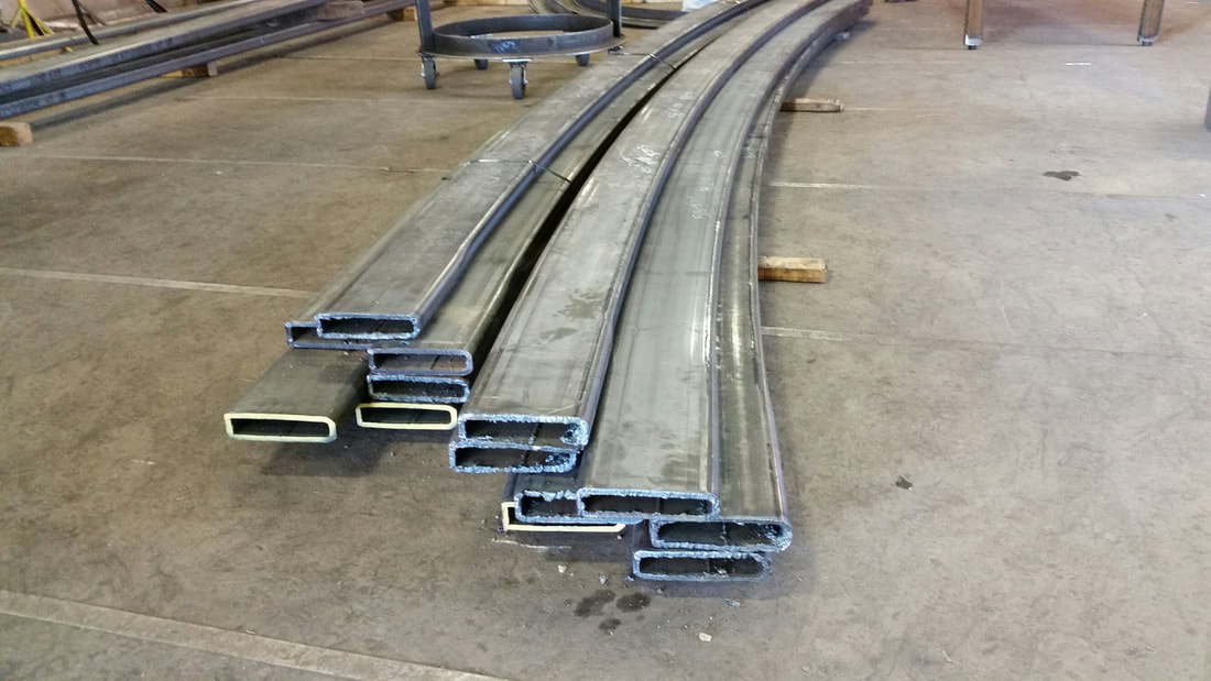 Image 8: 8" x 2" steel rectangular tubing bent to an outside radius of 58' 4" by Longero.
The curving track portion plus the third railing is still being designed, but we will most likely have it done by the end of this week (10/12/18).
We are also getting a lot of questions from other teams and would like to re-address them on here:
- Can we make the gap more than 4.8 inches?
- No, we are trying to keep the bogie as stable as possible. Also, the wooden track dimensions are NOT Futran dimensions, and for the steel portion we plan to use Futran dimensions because the bogie is designed accordingly to that.
- How will the wooden section and steel section (junction/ match up?
- The wooden section has different dimensions than the steel, but that should not be too much of a problem. As of now, we are going to use the beams made of sheet metal as shown in image 6 below. This cross section is 8x8 inches and we are planning to add whatever is necessary to the wooden track to match this cross section. The wooden track is made up of construction lumber with cross sections of 1.5x7 and 1.5x5.5. Also, the steel portion will be taller because it will include the third rail, but that should not be a problem with the wooden part because it does not need the third rail added.
Image 6 (left): The cross section we are planning to implement on the beam - Will the bogie be able to clamp onto the track?
- Yes! We are currently designing for this to be possible by changing the track. The cross-section that was provided by Futran is shown in image 7 below. This cross section is problematic because it will cost too much to manufacture, so we are using the cross-section shown in image 6 above. Image 8 below shows that the 8" x 2" rectangular steel tubing we are planning to use for the new cross-section design is capable of being curved to suit our junction and curved track sections.
Image 7 (left): The cross-section of the beam, taken from Futran's design Image 8: 8" x 2" steel rectangular tubing bent to an outside radius of 58' 4" by Longero.
Full Scale Bogie Team: I am happy to see some CAD work being completed. It would be nice to have a hand sketch of where this third rail is intended on being mounted on the guideway.
ReplyDeleteBy third rail, do you mean the conductive rail that the wayside needs in order to provide power to the bogie from the solar array? Or, is the third rail the steering rail that allows the bogie to change rails along the guideway?
To confirm, is your team planning on using last summer's wooden track and improving upon it?
Please read my latest postto ensure your team keeps up with Fqall 2018 schedule http://spartansuperway.blogspot.com/2018/10/fall-2018-week-by-week-schedule_8.html